I. What is a Centrifugal Air Compressor?
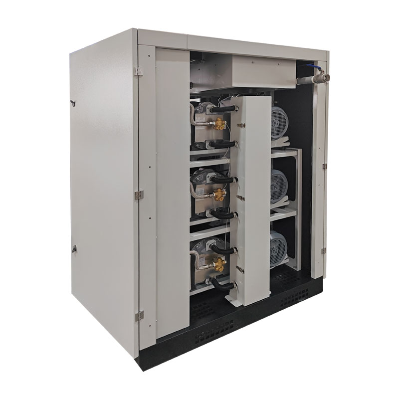
A centrifugal air compressor is a mechanical device that transports gas, consisting of a rotor, stator, and bearings. The rotor comprises a main shaft, impeller, coupling, and sometimes bushings and a smooth disc. The stator consists of a casing, interstage seals and shaft end seals, an intake chamber, and a volute.
A centrifugal air compressor is a type of turbine air compressor. Its working principle is completely different from that of a piston air compressor; it belongs to the rotary vane type of machinery.
II. The Working Process of a Centrifugal Air Compressor
When the electric motor drives the air compressor rotor to rotate through a speed increaser, air is drawn into the air compressor after mechanical impurities are removed by a filter. The air is compressed in the impeller and diffuser. Because the air temperature increases after compression, increasing the power consumption of the air compressor, it needs to be cooled by an intercooler before returning to the air compressor for further compression. After the final stage compression reaches the required pressure, it is sent to the air separation unit. The air compressor is lubricated by a dedicated oil station.
III. Working Principle of a Centrifugal Air Compressor
A centrifugal air compressor consists of an impeller and its associated fixed components forming one stage. When the motor drives the impeller to rotate, the gas inside the impeller chamber rotates with the impeller and is thrown out under the action of centrifugal force, increasing the gas pressure and its kinetic energy. Simultaneously, as the impeller's passage gradually widens from the inside to the outside, the relative velocity of the gas decreases as it flows from the impeller inlet to the outlet, thus converting some kinetic energy into increased pressure. After entering the diffuser from the impeller, the pressure further increases due to the further decrease in rotational speed; on the other hand, air enters the impeller chamber from the intake, filling the space left by the thrown-out air, continuously compressing the gas. Since the pressure increase that each impeller can provide is limited, the appropriate number of air compressor stages (i.e., the number of impellers) should be configured according to the required pressure. The air inlet of each impeller flows in axially, close to the axis. To ensure that the gas compressed in the previous stage enters the next stage, the airflow direction must be uniformly guided, through bends and recirculation.
The air compressor's six impellers are mounted on the main shaft to form a rotor, supported by bearings. The casing (cylinder) contains fixed components such as baffles, diffusers, elbows, and reflux devices. Air is introduced into the intake port of the first-stage impeller through the intake port. The impellers act on the gas, increasing its pressure and flow rate. The gas then flows to the diffuser, where its pressure is further increased. The gas is then diverted through the elbows and reflux device to the second-stage impeller. To reduce the temperature of the compressed gas, intercoolers are installed after the second and fourth stages. The DA200-61 air compressor can be divided into three stages, with the coolers as the boundary. Because it has six impellers, it is called a six-stage, three-stage compressor. Air from the stage with the cooler enters the intercooler through the diffuser and volute. After cooling, the air temperature is equal to or higher than the intake temperature of the first stage. It then continues to be pressurized in the third and fourth stages, flows to the second cooler, and then exits the intake chamber after cooling before entering the fifth stage. After passing through the sixth stage of final pressure, the air compressor flows out of the vortex chamber and enters the air separation unit after cooling.